Thursday, January 24, 2013

Hack A Toy!

 For this project, I will cut open a toy and salvage a motor and a sensor (a pushbutton). Using the tools learned in ELEC10, I will re-purpose the toy and control it using a microcontroller.

There is a start-up sound (Charge!). At every push of the button, a different song will play (up to three different songs: Tetris, Mission Impossible, and Mario Star Theme). When a song is playing, the mouth and eyes will move.


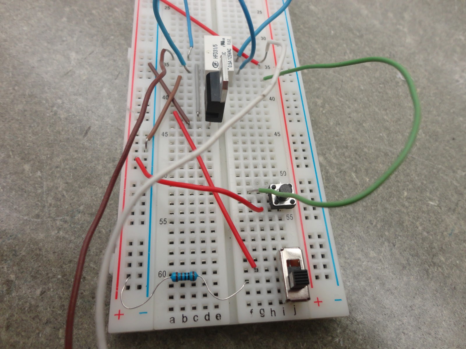
For the programming, I created a variable named "counter" to use the pushbutton switch (on the head) to increase the counter and change between modes. The motor has hardware stops preventing full rotation. Therefore I used a DPDT Relay to change the direction of the motor. On the breadboard is a yellow LED which is lit when a process is in progress. During this time, the switch will not increase the counter. A 100 Ohm resistor is used in series with the speaker. A 4.7kOhm connected to the pin and a 10kOhm resistor connected to ground is used on the switch operator. Lastly, a 2.2kOhm resistor is used for the TIP120 transistor, which amplifies the current enough to run the motor.

Below is the programming code used with the LaunchPad:

/*************************************************
 * Public Constants
 *************************************************/

#define NOTE_B0  31
#define NOTE_C1  33
#define NOTE_CS1 35
#define NOTE_D1  37
#define NOTE_DS1 39
#define NOTE_E1  41
#define NOTE_F1  44
#define NOTE_FS1 46
#define NOTE_G1  49
#define NOTE_GS1 52
#define NOTE_A1  55
#define NOTE_AS1 58
#define NOTE_B1  62
#define NOTE_C2  65
#define NOTE_CS2 69
#define NOTE_D2  73
#define NOTE_DS2 78
#define NOTE_E2  82
#define NOTE_F2  87
#define NOTE_FS2 93
#define NOTE_G2  98
#define NOTE_GS2 104
#define NOTE_A2  110
#define NOTE_AS2 117
#define NOTE_B2  123
#define NOTE_C3  131
#define NOTE_CS3 139
#define NOTE_D3  147
#define NOTE_DS3 156
#define NOTE_E3  165
#define NOTE_F3  175
#define NOTE_FS3 185
#define NOTE_G3  196
#define NOTE_GS3 208
#define NOTE_A3  220
#define NOTE_AS3 233
#define NOTE_B3  247
#define NOTE_C4  262
#define NOTE_CS4 277
#define NOTE_D4  294
#define NOTE_DS4 311
#define NOTE_E4  330
#define NOTE_F4  349
#define NOTE_FS4 370
#define NOTE_G4  392
#define NOTE_GS4 415
#define NOTE_A4  440
#define NOTE_AS4 466
#define NOTE_B4  494
#define NOTE_C5  523
#define NOTE_CS5 554
#define NOTE_D5  587
#define NOTE_DS5 622
#define NOTE_E5  659
#define NOTE_F5  698
#define NOTE_FS5 740
#define NOTE_G5  784
#define NOTE_GS5 831
#define NOTE_A5  880
#define NOTE_AS5 932
#define NOTE_B5  988
#define NOTE_C6  1047
#define NOTE_CS6 1109
#define NOTE_D6  1175
#define NOTE_DS6 1245
#define NOTE_E6  1319
#define NOTE_F6  1397
#define NOTE_FS6 1480
#define NOTE_G6  1568
#define NOTE_GS6 1661
#define NOTE_A6  1760
#define NOTE_AS6 1865
#define NOTE_B6  1976
#define NOTE_C7  2093
#define NOTE_CS7 2217
#define NOTE_D7  2349
#define NOTE_DS7 2489
#define NOTE_E7  2637
#define NOTE_F7  2794
#define NOTE_FS7 2960
#define NOTE_G7  3136
#define NOTE_GS7 3322
#define NOTE_A7  3520
#define NOTE_AS7 3729
#define NOTE_B7  3951
#define NOTE_C8  4186
#define NOTE_CS8 4435
#define NOTE_D8  4699
#define NOTE_DS8 4978

//Above is the library pitches.h

#define coil 3
#define motorHead 4
#define buttonPin 5
#define buttonLED 6
//pin 8 is audio

int buttonState = 0;  //define the variable for mouth switch
int counter = 0;
int melody1[] = 
{
  NOTE_G3,NOTE_C4,NOTE_E4,NOTE_G4,NOTE_E4,NOTE_G4
};  //Notes in the melody

int noteDurations1[] = 
{
  8, 8, 8, 4, 8, 1
};  //Note durations: 4 = quarter note, 8 = eigth note

int melody2[] = 
{
  NOTE_E4,NOTE_B3,NOTE_C4,NOTE_D4,NOTE_C4,NOTE_B3,NOTE_A3,NOTE_A3,NOTE_C4,NOTE_E4,NOTE_D4,NOTE_C4,NOTE_B3,NOTE_C4,NOTE_D4,NOTE_E4,NOTE_C4,NOTE_A3,NOTE_A3
};  //Notes in the melody

int noteDurations2[] = 
{
  4, 8, 8, 4, 8, 8, 4, 8, 8, 4, 8, 8, 3, 8, 4, 4, 4, 4, 4
};  //Note durations: 4 = quarter note, 8 = eigth note

int melody3[] = 
{
  NOTE_D4,NOTE_D4,NOTE_F4,NOTE_G4,NOTE_D4,NOTE_D4,NOTE_C4,NOTE_CS4
};
int noteDurations3[] = 
{
  2, 2, 3, 3, 2, 2, 3, 3
};  //Note durations: 4 = quarter note, 8 = eigth note

int melody4[] = 
{
  NOTE_F4,NOTE_F4,NOTE_F4,NOTE_D4,NOTE_F4,0,NOTE_F4,NOTE_D4,NOTE_F4,NOTE_D4,NOTE_F4,NOTE_E4,NOTE_E4,NOTE_E4,NOTE_C4,NOTE_E4,0,NOTE_E4,NOTE_C4,NOTE_E4,NOTE_C4,NOTE_E4
};

int noteDurations4[] = 
{
  4, 4, 4, 8, 8, 8, 4, 8, 8, 8, 4, 4, 4, 4, 8, 8, 8, 4, 8, 8, 8, 4 
};  //Note durations: 4 = quarter note, 8 = eigth note

void setup ()
{
  Serial.begin(9600);
  pinMode(coil, OUTPUT);   //initialize the coil as an output
  pinMode(motorHead, OUTPUT);   //initialize the motorHead as an output
  digitalWrite(motorHead, LOW);  //turn the Head Motor OFF
  pinMode(buttonPin, INPUT_PULLUP);    //initialize pin 5 as input
  pinMode(buttonLED, OUTPUT);          //initialize pin 6 as an output
  delay(500);
  for (int thisNote = 0; thisNote < 8; thisNote++)  //Plays "Charge"!
  {
    int noteDuration = 1000/noteDurations1[thisNote];  //calculate the note duration
    tone (8, melody1[thisNote], noteDuration);  //Play the note
    delay(noteDuration);  
  }
  digitalWrite(motorHead, HIGH); //turn on the motorHead
  digitalWrite(coil, HIGH);  //turn on the coil
  delay(3000);  //attempt to center the motor between the two hardware stops
  digitalWrite(motorHead, LOW);    //turn off the motorHead
  digitalWrite(coil, LOW);  //turn off the coil
  
}

void loop ()
{
  Serial.println(counter);
  buttonState = digitalRead(buttonPin);   //read the state of the pushbutton value
  if(buttonState == HIGH)
  {
    digitalWrite(buttonLED, HIGH);        //turn LED ON
    counter = counter + 1;                //increase the counter
    delay(1000);                          //pressing button only increases counter once
  }
  if(buttonState == LOW)
  {
    digitalWrite(buttonLED, LOW);          //turn the LED OFF
    counter = counter % 6;                 //set counter to the reaminder, range 0-3
  }
  
  ///////////////////////////////////////////////////////////////
  
  
  if(counter == 0)//Counter = 1, do nothing
  {
   digitalWrite(motorHead, LOW);
  }
  
  
   //Counter = 2, first mode, tetris
  else if(counter == 1)
  {
  digitalWrite(motorHead, HIGH);  //turn the Head Motor ON
  for(int i = 0; i < 1; i++)     //repeeat the song 'i' times
  {
  for(int thisNote = 0; thisNote < 19; thisNote++)
      {
      if(thisNote < 10)  //For half the song, power the motor one direction, else power opposite direction
      {
        digitalWrite(coil, HIGH);
      }
      else
      {
        digitalWrite(coil, LOW); 
      }
      int noteDuration = 1500/noteDurations2[thisNote];  //calculate the note duration
      tone (8, melody2[thisNote], noteDuration);  //Play the note
      delay(noteDuration);  
      }
  }
  digitalWrite(motorHead, LOW);  //turn the Head Motor ON
  counter = counter + 1;  //Increase the counter to a no-action state
  }
   
  else if(counter == 2)//first mode complete, do nothing
    {
    digitalWrite(motorHead, LOW);
    }
   
  //Counter = 3, second mode, mission imposible
  else if(counter == 3)
     {
    digitalWrite(motorHead, HIGH);  //turn the Head Motor OFF
    for (int j = 0; j < 2; j++)    //repeat the song 'j' times
    {
    for (int thisNote = 0; thisNote < 16; thisNote++)
      {
        if(thisNote < 8) //For half the song, power the motor one direction, else power opposite direction
      {
        digitalWrite(coil, HIGH);
      }
      else
      {
        digitalWrite(coil, LOW);
      }
      int noteDuration = 1000/noteDurations3[thisNote];  //calculate the note duration
      tone (8, melody3[thisNote], noteDuration);  //Play the note
      delay(noteDuration);  
      }
    }
      counter = counter + 1;//Increase the counter to a no-action state
    }
  
  else if(counter == 4)//second mode complete, do nothing
    {
    digitalWrite(motorHead, LOW);
    }

  //Counter = 4, third mode, mario star
  else if(counter == 5)
  {
    digitalWrite(motorHead, HIGH);  //turn the Head Motor OFF
    for (int k = 0; k < 4; k++)     //repeat the song 'k' times
    {
    for (int thisNote = 0; thisNote < 22; thisNote++)
      {
        if(thisNote < 11) //For half the song, power the motor one direction, else power opposite direction
      {
        digitalWrite(coil, HIGH);
      }
      else
      {
        digitalWrite(coil, LOW);
      }
      int noteDuration = 800/noteDurations4[thisNote];  //calculate the note duration
      tone (8, melody4[thisNote], noteDuration);  //Play the note
      delay(noteDuration);  
      }
    }
    counter = counter + 1; //Increase the counter to a no-action state
  }
}


Wednesday, January 23, 2013

Music and Advanced Programming

Playing music with a speaker!


void setup ()
{
}

void loop ()
{
  for (int pitch = 100; pitch<2000; pitch+=20)
  {
    tone(8, pitch, 10);
    delay(10);
  }
 
}


_____________________________________________________________________


/*************************************************
 * Public Constants
 *************************************************/

#define NOTE_B0  31
#define NOTE_C1  33
#define NOTE_CS1 35
#define NOTE_D1  37
#define NOTE_DS1 39
#define NOTE_E1  41
#define NOTE_F1  44
#define NOTE_FS1 46
#define NOTE_G1  49
#define NOTE_GS1 52
#define NOTE_A1  55
#define NOTE_AS1 58
#define NOTE_B1  62
#define NOTE_C2  65
#define NOTE_CS2 69
#define NOTE_D2  73
#define NOTE_DS2 78
#define NOTE_E2  82
#define NOTE_F2  87
#define NOTE_FS2 93
#define NOTE_G2  98
#define NOTE_GS2 104
#define NOTE_A2  110
#define NOTE_AS2 117
#define NOTE_B2  123
#define NOTE_C3  131
#define NOTE_CS3 139
#define NOTE_D3  147
#define NOTE_DS3 156
#define NOTE_E3  165
#define NOTE_F3  175
#define NOTE_FS3 185
#define NOTE_G3  196
#define NOTE_GS3 208
#define NOTE_A3  220
#define NOTE_AS3 233
#define NOTE_B3  247
#define NOTE_C4  262
#define NOTE_CS4 277
#define NOTE_D4  294
#define NOTE_DS4 311
#define NOTE_E4  330
#define NOTE_F4  349
#define NOTE_FS4 370
#define NOTE_G4  392
#define NOTE_GS4 415
#define NOTE_A4  440
#define NOTE_AS4 466
#define NOTE_B4  494
#define NOTE_C5  523
#define NOTE_CS5 554
#define NOTE_D5  587
#define NOTE_DS5 622
#define NOTE_E5  659
#define NOTE_F5  698
#define NOTE_FS5 740
#define NOTE_G5  784
#define NOTE_GS5 831
#define NOTE_A5  880
#define NOTE_AS5 932
#define NOTE_B5  988
#define NOTE_C6  1047
#define NOTE_CS6 1109
#define NOTE_D6  1175
#define NOTE_DS6 1245
#define NOTE_E6  1319
#define NOTE_F6  1397
#define NOTE_FS6 1480
#define NOTE_G6  1568
#define NOTE_GS6 1661
#define NOTE_A6  1760
#define NOTE_AS6 1865
#define NOTE_B6  1976
#define NOTE_C7  2093
#define NOTE_CS7 2217
#define NOTE_D7  2349
#define NOTE_DS7 2489
#define NOTE_E7  2637
#define NOTE_F7  2794
#define NOTE_FS7 2960
#define NOTE_G7  3136
#define NOTE_GS7 3322
#define NOTE_A7  3520
#define NOTE_AS7 3729
#define NOTE_B7  3951
#define NOTE_C8  4186
#define NOTE_CS8 4435
#define NOTE_D8  4699
#define NOTE_DS8 4978
#define LED 6

int melody [] =
{
  NOTE_C4,NOTE_G3,NOTE_G3,NOTE_A3,NOTE_G3,0,NOTE_B3,NOTE_C4
};  //Notes in the melody

int noteDurations[] =
{
  4, 8, 8, 4, 4, 4, 4, 4
};  //Note durations: 4 = quarter note, 8 = eigth note

void setup ()
{
  pinMode(LED,OUTPUT);
  delay(500);
  for (int thisNote = 0; thisNote < 8; thisNote++)
  {
    int noteDuration = 1000/noteDurations[thisNote];  //calculate the note duration
    if (thisNote != 5)
    {
    digitalWrite(LED,HIGH);
    }
    tone (8, melody[thisNote], noteDuration);  //Play the note
    delay(noteDuration/2);
    digitalWrite(LED,LOW);
    delay(noteDuration/2);
  }
}

void loop ()
{
}


Bi-directional Motor Control

DPDT Relay

Getting a motor to turn in both directions:


H-Bridge


If both LOW, no motors turn.
If #1 HIGH, #2 LOW, motor turns one direction.
If #1 LOW, #1 HIGH, motor turns opposite directions.
If Both HIGH, no motors turn.

H-Bridge didn't work with motors. Determined it was bad parts with debugging with Professor Mason.

Driving Motors and Other Output Devices

Introduction to 'standard' interfacing circuits, small current loads, medium current loads (motors)

Microcontroler controlling signal lamp

Using same code as previous post, digitalWrite(6,HIGH) > delay > digitalWrite(6,LOW) in a loop


Darlington controlling signal lamp
Darlington uses a MPSA42 medium power transistor. It nees 20mA to turn on completely. We will use a small signal transistor to turn on the power transistor.


MPSA13 low power PNP 30V 1.2A


Controlling motor in toy using TIP120


Microcontroller controlling motor


Microcontrollers, input and output

Input tranducers are electronic devices that detect changes in the real world and send signals into the process block of the electronic system: push switches, LDR, microphone, tilt switch, infared

First two videos were corrupted and could not be uploaded...

Demonstrate flashing LED with variable delay


#define LED 6

void setup()
{
  pinMode(LED,OUTPUT);              //Initialize Digital Pin 6 as output
    for(int counter = 20; counter > 0; counter = counter - 1)    //Definte the for loop
    {
      digitalWrite(LED,HIGH); //Set the LED ON
      delay(50 * counter);
      digitalWrite(LED,LOW); //Set the LED OFF
      delay(50 * counter);
    }
}
 
void loop()
{
  digitalWrite(LED,HIGH);            //Set the LED On
  delayMicroseconds(16000);          //Wait for 16 ms (1 second)
  digitalWrite(LED,LOW);             //Set the LED Off
  delayMicroseconds(16000);          //Wait for .016 seconds
}

Demonstrate pushbutton LED


#define buttonPin 5  //the number of the pushbutton pin
#define ledPin 6  //the number of the LED pin
int buttonState = 0;  //variable for reading the pushbutton status

void setup()
{
  pinMode(buttonPin, INPUT_PULLUP);  //initialize the pushbutton pin as an input
  pinMode(ledPin, OUTPUT);  //initialize the LED pin as an output
}

void loop()
{
  buttonState = digitalRead(buttonPin);  //read the state of the pushbutton value;
 
  if (buttonState == HIGH) //check if the pushbutton is pressed
  {
    digitalWrite(ledPin, HIGH); //turn the LED on
  }
  else
  {
    digitalWrite(ledPin, LOW);  //turn the LED off
  }
}


Demonstrate LDR controlling LEDs


#define sensorPin A0  //select the input pin for the LDR
#define ledPin6 6  //select the pin for the LED
#define ledPin7 7
int sensorValue = 0;  //variable to store the value coming from the sensor

void setup()
{
  pinMode(ledPin6, OUTPUT);  //declare the ledPin6 as an OUTPUT
  pinMode(ledPin7, OUTPUT);  //declare the ledPin7 as an OUTPUT
  Serial.begin(9600);
}

void loop()
{
  sensorValue = analogRead(sensorPin);  //read the value from the sensor
  Serial.println(sensorValue);
    if (sensorValue >= 565)
    {
      digitalWrite(ledPin6, HIGH);  //turn the ledPin on
      digitalWrite(ledPin7, HIGH);  //turn the ledPin on
    }
   
    else if (sensorValue < 565 && sensorValue >= 530)
    {
      digitalWrite(ledPin6, HIGH);  //turn the ledPin on
      digitalWrite(ledPin7, LOW);  //turn the ledPin on
    }
   
    else if (sensorValue < 530 && sensorValue >= 500)
    {
      digitalWrite(ledPin6, LOW);  //turn the ledPin on
      digitalWrite(ledPin7, HIGH);  //turn the ledPin on
    }
    else
    {
      digitalWrite(ledPin6, LOW);  //turn the ledPin on
      digitalWrite(ledPin7, LOW);  //turn the ledPin on
    }
}


Tuesday, January 22, 2013

Transistor Switching


Materials:
AC adapter
breadboard, wire, meter x2
LED
Resistors, various
Pushbutton, SPST
NPN Transistor 2N3904

Demonstrating a Fingertip Switch


A transistor is a current amplifier with a linear multiplier. Completed a test to prove this.
2x 180 Ohm resistors
2x 2K Ohm resistors


\


The beta gain of this transistor is approximately 4:


Introduction to Microcontrollers

Materials:
TIMSP430
Breadboard
Sufficient Wire
4 LEDs
4 Resistors between 200-500 Ohms, 220 is ideal

Demonstrating MSP430 Flashing LED:


Demonstrating LED Flashing Band (Nightrider)


void setup()
  {
    pinMode(6,OUTPUT); //Initialize Digital Pin 6 as an output
    pinMode(7,OUTPUT); //Initialize Digital Pin 7 as an output
    pinMode(8,OUTPUT); //Initialize Digital Pin 8 as an output
    pinMode(9,OUTPUT); //Initialize Digital Pin 9 as an output
  }

 void loop()
  {
    digitalWrite(6,HIGH);   //Set LED On
    delay(100);            //Wait for 1000 ms (1 second)
    digitalWrite(6,LOW);    //Set LED Off
    digitalWrite(7,HIGH);   //Set LED On
    delay(100);            //Wait for 1000 ms (1 second)
    digitalWrite(7,LOW);    //Set LED Off
    digitalWrite(8,HIGH);   //Set LED On
    delay(100);            //Wait for 1000 ms (1 second)
    digitalWrite(8,LOW);    //Set LED Off
    digitalWrite(9,HIGH);   //Set LED On
    delay(100);            //Wait for 1000 ms (1 second)
    digitalWrite(9,LOW);    //Set LED Off
    digitalWrite(8,HIGH);   //Set LED On
    delay(100);            //Wait for 1000 ms (1 second)
    digitalWrite(8,LOW);    //Set LED Off
    digitalWrite(7,HIGH);   //Set LED On
    delay(100);            //Wait for 1000 ms (1 second)
    digitalWrite(7,LOW);    //Set LED Off

  }


Tuesday, January 15, 2013

Switches and Relays

Task: Toggle Switch: similar to hallway light, each switch will turn LED on or off

(Schematic Goes Here)


Task: Create a circuit using pushbutton and relay. Push button will switch LED from lighting Red LED to lighting Green LED. Data sheet of the relay can be found here: http://www.hongfa.com/pro/pdf/HFD31_en.pdf


Task: A relay Oscillator. Now, the contacts in the relaxed state feed power to the coil as well as to one of the LEDs, but then it energizes the coils and opens the contacts making a very quick cycle. It oscillates 50 times/second. Only press it very briefly because it is likely to burn itself out or destroy.


Task: Adding capacitance. Add a capaciter to the circuit so that when the pushbutton is pushed, the LEDs alternate just like a car blinker light.

Schematics, Ohm's Law and Potentiometers

Introduction to Schematics and Data Sheets

Task: Find minimum resistance at data sheet Forward Voltage to produce brightest LED.

Calculation: [(Power supply) 5.15V - (LED Foward Voltage) 1.85V] /[(Current)/.02A] = 165 Ohm

Find next highest resistor, reduce cost and production time (real life). In my schematic, used 2 resistors in series to make 165 Ohm. Attach to Potentiometer to produce "Dimmer Light"


Thursday, January 10, 2013

Solderless Breadboard, Effect of Resistance on LED

Summary: Created simple circuit with a Light Emitting Diode (LED) and various resistors

Above: Circuit with LED and 100 Ohm Resistor
Above: Circuit with LED and 1000 Ohm Resistor
Above: Circuit with LED and 10000 Ohm Resistor
 *In a LED, the positive lead is the slightly longer lead. LEDs will not work when backwards.
*Resistors can be read by their colors. Resistors can work backwards  Also, it does not matter the order in which the resistor is placed.
*The higher the resistor/resistance, the less bright the LED will emit.


Using a Multimeter, Testing Potentiometer (Pot) and Light Dependent Resistor (LDR)

Summary: We learned to conduct continuity measurements, resistance measurements, and voltage measurements using a Multimeter.

Above: Pot with minimum resistance

Above: Pot with maximum resistance


*Potentiometer maximum was 9.57 kOhm
*If opposite adjacent pins are connected, resistance is opposite of the range
*When pot is centered, resistance was half, therefore linear


Above: LDR with room light

Wednesday, January 9, 2013

5V Breadboard Power Supply

Task: Construct a 5V Breadboard Power Supply

Using a BlackBerry PSM04A-050RIM 5V 0.75A MiniUSB Charger, cut the MiniUSB side off. Splice the ends. Solder a butt joint to a 2 .1" prongs. Finish with heat shrink.


Test for polarity with a multi-meter. Connection was good and this will be used for future projects.